
Part 6 CAD Design
Functions for design in CAD
Part 6
The functions in the Edit menu
Contour start posn
Align position
Delete position
Insert position
Displace Position
Replace by straight line (Linearise)
Replace by corner
Replace by circle3P
Replace by arc
Replace by rect. / ..full circ. / ..Ellipse
Replace by drilling
Interpol. edit
Round-off corner
Corner in frame
Cut corner
Contour section
Undo vector
Delete vector
Delete sections
Join sections
Join posn
Separate posn
Add posn
The functions in the Edit menu. |
 |
The functions available in your program are dependent on your program configuration and can deviate from this description. Current information on the operation of the functions can always be obtained using the program help. |
2D graphic data, in particular scanner data, are revised in the Edit menu. Scanner data are mostly very comprehensive and possess small irregularities conditional on the digitalisation process. It is precisely large data sets which demand large working times for further processing. in this menu there are effective functions contained, which improve the quality of the data set considerably with small operation and time expenditures.
The Edit is divided into 2 ranges. The upper range Contour start posn to Contour crop is configured for reworking contour data (scanner data). The functions in this range are configured for the processing of closed contours . The lower range Disconnect vector to Append posn serves for reworking sections. These functions can be applied to both contours and also to sections.
| Contour start posn |
Start point of a contour (click-on new point). The track start position can be replaced by any desired position. For this, the desired track must be selected using the cursor. This track and the instantaneous start position are marked. following the display
Select position
Any desired point on this track can be selected using the cursor, which after pressing the key ismarked and is adopted as new start position. aborts the input.
This function is not suitable for sections and therefore, in this case, be aborted with an error message.
| Align position |
Adjust several positions on a line. Using this function any desired positions, which can lie on different tracks, can be adjusted in one line. The coordinates of the original (not yet displaced reference point) are displayed in the input line.
For this
- a reference point is selected and possibly displaced to a new position,
- a line (rule) is input,
- The point which is to be displaced vertically on the rule, is clicked-on.
The input is ended using or .
Input position (x,y):
A reference point is selected as first input using the cursor. The reference point is a point lying on any desired track.
Displace reference point (=NO):
The reference point can, as required, be displaced in that a new position is input using the cursor or keyboard. If is pressed then the reference point remains unchanged. A line is drawn through the reference point.
Reference point XY [mm] or angle [deg.]:
The direction of the line is determined by the input: a 2nd reference point using the cursor, a 2nd reference point via the keyboard or a direction via the keyboard in deg. With keyboard input the input of a figure in the range -360 .. 360 deg. is assessed as angle and the input of two figures as X and Y value of the 2nd reference point. No or an invalid input determines the cursor position as 2nd reference point. With the input using the graphic cursor the line is permanently codrawn until acknowledged using . The function is cancelled with input using .
Following confirmation of input the line is drawn as reference rule. Now any desired number of positions, which are to lie on the rule, can be selected using the cursor and the key . The positions are always displaced vertically to the rule. All set positions are redrawn. An operation of the key ends the input.
| Delete position |
Delete one or more support points in a contour. If the start and end points in an open section are deleted, this can lead to errors because the section is closed.
If only one point is clicked-on, then only this is deleted. If a frame is drawn around several support points of a contour, then all points within the frame are deleted.
| Insert position |
Insert a point between 2 end points of a vector. A single position is introduced into a contour or a section. For this the vector (not the end point) is to be clicked-on, in which the new position is to be added. The so created angle can be displaced as desired using the cursor. If, following the vector selection, the input is aborted using , then a point is introduced on the vector without creating an angle.
| Displace position |
Displace one or more support points. If only one point is clicked on then only this is displaced. If this point is a 3D position, then the 3D coordinates can be edited after displacement. If a frame is drawn around several support points of one or more contours, then all points within the frame are displaced. The coordinates of the original (still not displaced point) is displayed in the input line.
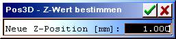
Selection of the function using in the icon menu.
Convert one or more support points into 3D positions and determine the Z value. If only one point is clicked on, then its Z value is displayed and can be modified. If a frame is drawn around one or more support points then all points lying within the frame are set to the given value.
If the graphic was previously 2D(normal case), then the Z values of the lines (milling depths) are at first undetermined and are first set to a certain milling depth(s) for milling. If only individual points of this graphic determined, then the remaining points continue to remain undetermined in Z and are first determined for milling tasks by means of the tool data. If you are unsure of the operation then you should determine all points of the contour.
Start and end points of closed contours or double points cannot be deliberately marked individually. In order to determine securely all multiple points in Z, you should in this case mark the points with a frame.
| Replace by straight line (linearisation) |
 |
Replace the section between 2 points with a straight line. There must be a 3rd point available between these two points for section selection. Using this function unwanted positions can be removed from a track. To input a straight line 3 points are required. First, one after the other, both the end positions, which are to be joined by a straight line, are selected using the cursor. As further input one position is demanded between these support points. |
| Replace by corner |
 |
Replace the section between 2 points with an angle. A 3rd point must be present between these points. With this an angle can be newly positioned and unwanted positions can be removed. For the correction of an angle 3 points are required. First, one after another, the two end positions must be input using the cursor. A position between these support points is demanded as further input. Following this input the angle is drawn using 2 lines and can now be freely positioned using the cursor. |
| Replace by circle3P |
 |
Replace the section between 2 points with an arc. A 3rd point must be present between these points. The resolution of the arc is determined through Input parameter . Circ. resolution.
Both end points are required for the input. A position between these support points is demanded as further input. By moving the position using the cursor an arc is also drawn which is formed by both end points and the middle position. |
| Replace by arc (HCAM only) |
 |
Replace the section between 2 points with a parabola (fit curve). A 3rd point must be present between these points. With simultaneous pressing of a curve (Spline4) is created with tangential transitions to the junction points. The resolution of the arc is determined through Input parameter . Spline resolution |
| Replace by rect. / replace by full circ. / replace by ellipse |
 |
Replace one or more contours with a rectangle, a full circle or an ellipse with correct position and elongation. If only one contour is clicked-on, then only this is replaced, whereby the original direction of rotation is retained. If a frame is drawn around several contours the all contours are replaced with a rectangle, a full circle or an ellipse, whose direction of rotation must be determined. |
| Replace by drilling (HCAM only) |
 |
Green: contours before replacement by drillings.
Replace one or more paths (sections or contours) with drillings. If only one path is clicked-on, then this is replaced with a drilling, which lies in the centre of the path. If a frame is drawn around several paths then all paths are replaced respectively by one central drilling. |
| Interpol.Edit (HCAM only) |
 |
 |
Edit and replace the section between 2 points using a complex spline. For input 3 points are required. First, one after another, both end positions must be entered using the cursor and after this a position input between these positions. The curve supporting points, as well as start and end slopes can be edited. The start and end positions are not changed. |
| Delete position: | Delete a support point in the curve. |
| Insert position: | Insert a new point in the curve. |
| Displace position: | Displace a support point. |
| Approximate: | Approximate the curve, i.e. smooth and insert new support point. |
| Reduce: | Coarsen the curve, i.e. remove support points. |
| Adopt sup. pt: | Adopt the edited support points in place of the original curve. |
| Adopt spline: | Vectorise the spline curve and adopt in place of the curve. |
| Abort: | Abort the input, the curve remains unchanged. |
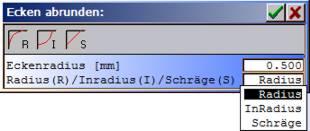
| Round-off corner |
 |
 |
Round-off a corner made from 2 vectors or provide with a chamfer. If one or both corner vectors are too short, then no rounding-off or chamfer is created. In this case a clean corner must be created beforehand.
The circular radius or separation of the chamfer from the corner and the function radius, inradius, chamfer must first be input. Thereafter any number of desired corners can be selected using the cursor. The function is ended if, during the display
Input position
key is pushed.
| Corner in frame (HCAM only) |
 |
Form a corner from vectors which cut the cursor rectangle. Multiple positions, which lie in a rectangle, are replaced by a corner. For this, instead of the cursor cross a rectangle is overlaid in the graphic area. This frame must now be so positioned, that the positions which are replaced by a corner, are to lie within the frame. For the formation of a new corner at least 2 positions must be input. If only one position is aligned, the input is ignored and there follows no further processing. This function is applicable for closed contours only. |
The frame size can be modified in that the key is pressed and the desired dimensions are drawn using the cursor. Only positions of the track to processed may lie in the frame. If possible several contours lie within the input rectangle, then the desired contour should be marked previously using the select aid. If contours are marked, then corners are formed using the marked corners only.
After pushing the key a new corner is calculated and adopted. If the new corner lies further than one side length of the square removed from the input position, then the following safety question arises before the final adoption in the input line:
Adopt Y/N ?
| Cut corner |
 |
Cut 2 vectors together in a contour and replace the section lying between these vectors with a corner. The corner (section) lies in the run direction between the 1st and 2nd vector. |
| Contour section (HCAM only) |
Depending on the selection of the end points a contour can be separated into 2 contours or two contours are joined. The contours must always be closed.
The cut is to be selected using 2 points on the contour(s). If the points lie on a contour, then 2 closed contours are created from these on the intersection line. If the points lie on 2 separate contours, then these are joined on the intersection line.

| 1 | 2 | 3 | 4 | 5 |
Results with contour cut:
| 1 | Original contour. |
| 2 | Contour cut, result: 2 contours. |
| 3 | Both contours reduced in size inwards using offset. |
| 4 | Both contours with 2 contour cuts rejoined. result is one outer contour and one inner contour. |
| 5 | Inner and outer contour separated. |
| Undo vector (HCAM only) |
 |
Undo a vector at a point (insert PosnA), which are clicked-on using the cursor. Each contour or section is thus divided into 2 sections. The separation points can be displaced individually using Displace position. |
| Delete vector (HCAM only) |
 |
Delete a vector in a contour or section (interrupt). For this the track/section is broken open. |
| Delete section (HCAM only) |
 |
Delete a section between 2 points (interrupt). A 3rd point must be present between these points for the section selection. A part of a track is deleted, i.e. the track is separated. Using this function unwanted positions can be removed from a track. |
| Join sections (HCAM only) |
 |
Individual polygon runs (sections), which are not closed, can be joined together. For this, first the 1st section is clicked on, a line is drawn to the 2nd section and this is also clicked on. |
On the command End point 1 the first section to be combined is to be clicked-on using the cursor. The section is marked and connection from the end point of the section is drawn to the cursor. The connection is also carried with every cursor movement.
On the command End point 2 the second section is to be clicked-on using the cursor, which is to be joined the first section. The second section is marked the connection from the end point of the first section is drawn to the start point of the second section.
| Join posn |
Join two positions. The selected start point is joined to the nearest position. If the separation to the nearest support point is less than 0.02 mm, then the support points are laid on top of each other. If the separation is larger then a joining vector is inserted.
| Separate posn |
Separates a path at a support point and sets a new start point (PosnA).
| Add posn (HCAM only) |
Attach a vector (line) to a section. After clicking on a section start or end point input a further support point using the cursor and, after confirmation using , join to the section. For this, the section is so turned that the point on which it is to be joined, lies at the end. After attachment of a position further input can be made also in the Draw menu.